


- 充電コネクタ
- エネルギー贮蔵コネクタ
- テレコムコネクタ
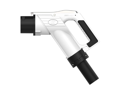
- EVコネクタ
- ワイヤーハーネス
𐄀 未来へのテクノロジー接続


電気回路図
YG 762 DC車両コネクタのモデルの詳細 (この仕様は次の表のモデルに適用されます)。 | |||||||||||
いいえ。 | 名前 | ポート配線仕様 (mm ²) | |||||||||
DC | DC- | PE | A | A- | CC1 | CC2 | S | S- | |||
1 | YGC762-EV-P9P-80プラグ | 20 | 20 | 25 | 4 | 4 | 0.75 | 0.75 | 0.75 | 0.75 | |
2 | YGC762-EV-P9P-125プラグ | 35 | 35 | 25 | 4 | 4 | 0.75 | 0.75 | 0.75 | 0.75 | |
3 | YGC762-EV-P9P-160プラグ | 50 | 50 | 25 | 4 | 4 | 0.75 | 0.75 | 0.75 | 0.75 | |
4 | YGC762-EV-P9P-200プラグ | 70 | 70 | 25 | 4 | 4 | 0.75 | 0.75 | 0.75 | 0.75 | |
5 | YGC762-EV-P9P-250プラグ | 80 | 80 | 25 | 4 | 4 | 0.75 | 0.75 | 0.75 | 0.75 | |
6 | YGC762A-EV-P9P-125プラグ | 35 | 35 | 25 | 4 | 4 | 0.75 | 0.75 | 0.75 | 0.75 | |
7 | YGC762A-EV-P9P-160プラグ | 50 | 50 | 25 | 4 | 4 | 0.75 | 0.75 | 0.75 | 0.75 | |
8 | YGC762A-EV-P9P-200プラグ | 70 | 70 | 25 | 4 | 4 | 0.75 | 0.75 | 0.75 | 0.75 | |
9 | YGC762A-EV-P9P-250プラグ (250A超音波) | 70 | 70 | 25 | 4 | 4 | 0.75 | 0.75 | 0.75 | 0.75 | |
10 | YGC762A-EV-P9P-250プラグ | 80 | 80 | 25 | 4 | 4 | 0.75 | 0.75 | 0.75 | 0.75 | |
Adaptケーブル | |||||||||||
いいえ。 | 仕様カチオン | 適応ケーブル仕様 | ケーブルコア数 | OD (mm) | |||||||
1 | 80A | TPE 2x20mm2 25mm2 2x4mm2 2xP(2x0.75mm2) P(6x0.75mm2) | 15 | Φ 32 ± 1 | |||||||
2 | 125A | TPE 2x 35mm2 25mm2 2x4mm2 2xP(2x0.75mm2) P(6x0.75mm2) | 15 | Φ 36 ± 1 | |||||||
3 | 160A | TPE 2x50mm2 25mm2 2x4mm2 2xP(2x0.75mm2) P(6x0.75mm2) | 15 | Φ 36.5 ± 1 | |||||||
4 | 200A | TPE 2x70mm2 25mm2 2x4mm2 2xP(2x0.75mm2) P(6x0.75mm2) | 15 | Φ 40 ± 1 | |||||||
5 | 250A | TPE 2x 80mm2 25mm2 2x4mm2 2xP(2x0.75mm2) P(6x0.75mm2) | 15 | Φ 40 ± 1 | |||||||
6 | 80A | TPE 2x20mm2 25mm2 2x4mm2 2xP(2x0.75mm2) P(7x0.75mm2) | 16 | Φ 32 ± 1 | |||||||
7 | 125A | TPE 2x 35mm2 25mm2 2x4mm2 2xP(2x0.75mm2) P(7x0.75mm2) | 16 | Φ 36 ± 1 | |||||||
8 | 160A | TPE 2x50mm2 25mm2 2x4mm2 2xP(2x0.75mm2) P(7x0.75mm2) | 16 | ||||||||
9 | 200A | TPE 2x70mm2 25mm2 2x4mm2 2xP(2x0.75mm2) P(7x0.75mm2) | 16 | Φ 40 ± 1 | |||||||
10 | 250A (超音波溶接) | TPE 2x 70mm2 25mm2 2x4mm2 2xP(2x0.75mm2) P(7x0.75mm2) | 16 | Φ 40 ± 1 | |||||||
11 | 250A | TPE 2x 80mm2 25mm2 2x4mm2 2xP(2x0.75mm2) P(7x0.75mm2) | 16 | Φ 40 ± 1 | |||||||
注意 | |||||||||||
★上記は一般的な製品モデル、配線、ライン直径の要件に従って選択してください、カスタマイズされた要件がある場合は、当社にご相談ください。 ★カスタマイズされた製品のケーブルハーネスは、実際のアプリケーションに応じて特定のモデルである必要があります。詳細については、当社に相談してください。 | |||||||||||
電気パラメータ | ポート定義 | DC ± | PE | ± A | CC1 | CC2 | S ± | ||||
配線仕様 (ユニット: Mm2) | 25 | 35 | 70 | 70 | 80 | 25 | 0.75 ~ 4 | 0.75 | 0.75 | 0.75 | |
コンタクトターミナル直径 (Mm) | Φ 12 | Φ 6 | Φ 3 | Φ 3 | Φ 3 | Φ 3 | |||||
定格動作電圧 (DC) | 750V/1000V | / | 0 ~ 30V | 0 ~ 30V | 0 ~ 30V | 0 ~ 30V | |||||
現在の評価 (DC) | 80A | 125A | 200A | 250A | 250A | / | 2 ~ 20A | 2A | 2A | 2A | |
接触抵抗 | ≤ 0.3mΩ | ≤ 0.4mΩ | ≤ 3mΩ | ||||||||
絶縁抵抗 | ≥ 2000MΩ(1000V AC) | ||||||||||
圧力に耐える (50Hz、 AC通常) | プラグの配線の後のテスト: ① DCとDC-3500V AC间の抵抗电圧1min; ① DC、DC-およびPE、S、S、A、A-抵抗電圧1500V AC 1分; ① PEおよびS、S-、A、A-それぞれ抵抗電圧1500V AC 1分; ① S、S-、CC1、A、A-1500V AC 1分の2つの抵抗電圧。 ソケットiの後のテストS有線: ① DCとDC-3500V AC间の抵抗电圧1min; ① DC、DC-およびPE、S、S-、CC1、CC2、A、A抵抗電圧1500V AC 1分; ① PEおよびS、S-、CC2、A、A抵抗電圧1500V AC 1min; ① S、S-、CC2、CC1、A、A-1500V ACの2つの相互電圧抵抗1min | ||||||||||
機械性能パラメータ | サービス寿命: | 10000回 | |||||||||
| 挿入力: | <140N | ||||||||||
| ロックイン力: | 200N | ||||||||||
环境パフォーマンスパラメータ | 挿入前: | YG 762 / YG762A IP54; | |||||||||
| 挿入後: | YG 762 / YG762A IP55; YG762A電気部品はIP67に達することができます (ソケットとの接続インターフェイスを除く)。 | ||||||||||
| 注: | テール配線曲げ半径 <6ケーブルODを避けてください | ||||||||||
| 周囲温度: | -30 ℃ ~ 50 ℃ | ||||||||||
素材 | エンクロージャ: | エンジニアリングプラスチック (高性能PC) | |||||||||
| ターミナル: | 銅、表面メッキシルバー/ニッケル | ||||||||||
| シール部品: | シリコーンゴムまたは弾性绝縁材 | ||||||||||
| 难燃性グレード: | UL94 V-0 | ||||||||||
実装基準 | GB / T 18487.1-2015 EV-パート1: | 一般要件 | |||||||||
| GB / T 20234.1-2015電気自動車の導電性充電のための接続デバイス-パート1: | 一般要件 | ||||||||||
| GB / T 20234.3-2015 EV伝送充電のための接続; パート3: | DC充电インターフェース | ||||||||||
電気原理 | 各端末の関数定义: | ||||||||||
いいえ。 | ターミナル識別 | 関数の定義 | |||||||||
| 1 | DC | DC電源は正であり、DC電源はバッテリーカソードに接続されています | |||||||||
| 2 | DC- | DCパワーはマイナスであり、DCパワーはマイナスであり、バッテリーはマイナスであることを接続する | |||||||||
| 3 | PE | 保護グラウンド (PE) 、電源装置のアース線と車体のアース線に接続します | |||||||||
S | 充電通信CAN _ H、非オンボード充電器と電気自動車の間の通信回線を接続する | ||||||||||
| 5 | S- | 充電通信CAN _ L、非オンボード充電器と電気自動車の間の通信回線を接続する | |||||||||
| 6 | CC1 | 充電接続確認1 | |||||||||
| 7 | CC2 | 充電接続確認2 | |||||||||
| 8 | A | 低電圧補助電源は、電気自動車用の非オンボード充電器によって提供される低電圧補助電源に接続されています | |||||||||
| 9 | A- | 低電圧補助電源はマイナスで、電気自動車用の非オンボード充電器によって提供される低電圧補助電源に接続されています | |||||||||
| 10 | T1 | 温度センサーはDC電源の右側にプラスです | |||||||||
| 11 | T1- | DC側の温度センサーはマイナスです | |||||||||
| 12 | T2 | DC電源のマイナス側温度センサーはプラスです | |||||||||
| 13 | T2- | 温度センサーはマイナス面でマイナスです | |||||||||
★T1-and T2-are利用可能 | |||||||||||
| 14 | 12Vの电子ロック | 車のコネクターの電子ロックは肯定的です | |||||||||
| 15 | 电子ロックGND | 車のコネクターの中の電子ロック | |||||||||
| 16 | 电子ロックフィードバック サイン | 車両コネクタの電子ロックが機能し (ロック解除/ロック) 、フィードバックは肯定的です | |||||||||
| 17 | 电子ロックフィードバック サイン- | 車のコネクターの電子ロックは働き (ロック解除/ロック) 、フィードバックは否定的です | |||||||||
★电子ロックGNDと电子ロックフィードバックSIGN-availabl | |||||||||||
車のコネクターのための付属品 | 1. YG762プラグ保護カバーアセンブリ (オプション): | ||||||||||
 | |||||||||||
★モデル: 要求に応じて注文するYG 762-01-02-00 (112980000706) 、注文比率は1:1 (プラグ: YG 762プラグ保護カバーアセンブリ)。 | |||||||||||
2. YG 762電磁ロックアセンブリ (必須): | |||||||||||
YG 762 (普通開いて、普通閉まる) YG 762-01-01-00 (112980000700クローズ) YG 762-01-01-00 / 01 (112980001628レギュラーオープン) | Y G762A電子ガンロック (通常開いて、 通常閉じた) 501021703907 (モーター电子ロック) 501021703906 (モーターロック) | ||||||||||
 |  | ||||||||||
★モデル: 要求に応じて注文、注文比率1:1 (プラグ: 電磁ロックコンポーネント)。 | |||||||||||
3. PCBAの制御板アセンブリ (任意): | |||||||||||
 | |||||||||||
★モデル: 需要に応じた注文、注文比率1:1 (プラグ: PCBAコントロールボードアセンブリ) YG762-01-12-00(112980001149)0.4M YG762-01-12-00/01(112980002602)1.5M YG762-01-12-00/02(111009802061)1.5Mバンドターミナル | |||||||||||
4.温度センサー (必要): | |||||||||||
| A) 温度センサーPT1000 (Φ 3.010mm) (501021701034) サイズ抵抗テーブル:
温度補正係数: 7 ℃ (端末の実際の温度 = センサー温度7 ℃) | |||||||||||
B) 温度センサーNTC 10K 3950 (501021702315) 寸法抵抗テーブル:
温度補正係数: 7 ℃ (端末の実際の温度 = センサー温度7 ℃) | |||||||||||
C) NTC 3435 10KΩ (501021701772) | |||||||||||
D) 温度スイッチ (90 ± 5 ℃ オフ) (501021701036) 抵抗テーブル | |||||||||||
E) 温度スイッチ (100 ± 5 ℃ オフ) (501021702297) | |||||||||||
★プラグは、標準に従って、DC / DCで2つのセンサーまたは温度スイッチを選択します。 | |||||||||||
5.空の座席 (オプション): | |||||||||||
YG349-02-00-00KR |
YG762-50-00-00KR | ||||||||||
★モデル: YG 349-02-00-00 KR (11298000000394) YG 762-50-00-00 KR (111000500836) ★需要に応じて選択し、プラグの注文、注文比率1:1 (プラグ: 空席) と一致します ★要求に応じて、テールラインをコネクタに接続することができます。 | |||||||||||
| 6. YG762A。 シンプルな緊急ロック解除レバー (オプション): | |||||||||||
 | |||||||||||
★モデル: YG762シンプルな緊急ロック解除ロッド (114039803419) ★需要に応じて、プラグで注文し、実際の状況に応じて充電パイルサイト。 | |||||||||||
お知らせ情報 | 説明: ★発表ロゴはモデルテーブル「name」に対応しています ★注: プラグタイプのソケットの発表はありません、私達の会社は実際の状況に従って増加します | ||||||||||
発表ロゴ | 温度制御装置 | エレクトロマグ ネティックロック デバイス | 強力な検査 レポート番号 | CQCレポート番号 | |||||||
YGC762-EV-P9P-80 | 持っている | 持っている | QA16EE1EB4141 QA16EG1EB4141 | QA16XX1EFC341 | |||||||
YGC762-EV-P9P-125 | 持っている | 持っている | QA16EE1EB4141 QA16EG1EB4141 | QA16XX1EFC341 | |||||||
YGC762-EV-P9P-200 | 持っている | 持っている | QA16EE1EB4141 QA16EG1EB4141 | QA16XX1EFC341 | |||||||
YGC762-EV-P9P-250 | 持っている | 持っている | QA16EE1EB4141 QA16EG1EB4141 | QA16XX1EFC341 | |||||||
YGC762A-EV-P9P-80 | 持っている | 持っている | QA18EE1XZ5471 | C QC20029252191 | |||||||
YGC762A-EV-P9P-125 | 持っている | 持っている | QA18EE1XZ5471 | C QC20029252191 | |||||||
YGC762A-EV-P9P-200 | 持っている | 持っている | QA18EE1XZ5471 | C QC20029252191 | |||||||
YGC762A-EV-P9P-250 | 持っている | 持っている | QA18EE1XZ5471 | C QC20029252191 | |||||||
YG 762製品の雨水環境への暴露を禁止します。
充電ソケットを使用するとき:
(1)車のコネクター挿入されて立ち往生している、ソケット穴に異物掘削があるかどうかを確認します。 検査後に異物がない場合
方法通常のプラグとプル、処理のためのメーカーに連絡してください。
(2) 絶縁不良を報告するときは、まずバッテリーサービススイッチが切断されていることを確認し、必要に応じて車体回路システムのメインゲートを閉じます。
ソケットが漏れているかどうかを確認し、水漏れがある場合は、最初にマルチメーターで拭いて、端子間の絶縁を検出します
抵抗 (PEとCC1を除く) 、2000M Ω の抵抗値は正常です、そうでなければ治療のためにメーカーに連絡してください。
(3) 異常な充電接続の場合、バッテリーサービススイッチが切断された状態にあることを確認し、必要に応じてボディ回路システムを閉じます
ゲート全体については、PEとCC1の間の抵抗値を検出します。抵抗値が1000 / -30 Ω であれば、それ以外の場合は接触します。
メーカー処理;
(4) 充電インターフェースをアルコール、特にソケット内の金属ジャックで定期的に拭いて清掃します。

独自のニーズに合わせてコネクタを調整します。
全身ソリューションを提供
12時間以内にニーズに対応


 英語
英語  日本語
日本語  Deutsch
  ไทย
ไทย  русский
  العربية


